| Introduction: |
The Dektak 150 is a contact surface profilometer which uses a mechanical stylus to determine surface profiles. Specifically, a 12.5µm radius tip is lowered into contact with the substrate, with a force adjustable from 1 to 15mg. Then the substrate will move toward the operator in the horizontal plane over a distance of up to 55mm. Maximum vertical deflection is 500µm. This is a manually controlled, not automated, version.
Typical usages of surface profilometers include measurement of films deposited or etched, surface roughness and radius of curvature of the substrate. |
| Procedure: |
Standby Condition at Beginning and End of the Run:
PC is on, but Dektak software is closed, door is closed, and CORAL disengaged.
- Engage in CORAL, which will turn the computer monitor ON.
- Run Dektak software.
- Open door and load sample on chuck, with measurement point directly under the tip. Note the stage moves in X and Y direction slowly with the knobs, or quickly with the release clamps. Stage also rotates manually.
Reminders:
- Only essentially flat substrates allowed, without fixtures, unless staff is assisting.
- Maximum of 500µm step heights
- Small samples may be placed on a slide to ease handling.
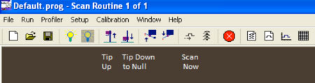
- Dektak software opens in the “Tip Positioning” window, with a row of icons on top. Identify the icon “Tip Down to Null”, and click it to bring the tip down to the substrate, briefly, before it raises the tip ~.5mm above the substrate, to allow sample positioning via the monitor camera display. Adjust the sample position such that when the sample travels down on the monitor, the feature to be measured will travel through the center cross. Close door after positioning sample.
- Note the center cross extends outwards ~220µm from center, useful for selecting scan length.
- Find and click the “Scan Routine” icon, then click on any of the scan parameters in the top left of the screen. The screen will display many parameters, some of which are true machine variables, but some of the displayed items are solved based on the inputs selected. Tip radius is fixed at 12.5µm. For instance, the machine samples 300 points per second, so the number of points is a factor of seconds.
Real input values
- Scan Length. Choose 10 to 55000µm (that is 55mm)
- Scan Duration. Choose at least 4 seconds, longer times give less bouncing and more data.
- Contact Force. 1-15 milligrams, with lower force for soft films, at the risk of more bouncing.
- Scan Range. Choose less than 6.5µm, <65µm, or <650µm, whichever your sample’s step height is closest to, without going over. For instance, the accuracy of a 40µm high step of an SU8 line would be better if the 65µm scale was selected, vs. the 650µm scale. The 6.5µm scale would fail due to the actual height being greater than the scale’s maximum deflection in this example.
- Hills, Valleys, or Both. Allows reading over the selected Scan Range to be biased, with 80% of the range available upward for Hills, downwards for Valleys, or equal for Hills & Valleys. In the example under (4), above, if Hills was selected, the vertical limit would not be reached (80% x 65µm = 52µm), but it would fail with the other selections.
- Find & click the “Sample Positioning” icon to return to the camera display window, and find and click the icon “Run Currently Active Scan”, which will cause the scan to start, displaying a profile of the substrate as it is moving towards you under the tip. The tip will come into contact with the substrate, and then retract to the “Null” position, .5mm above the substrate.
- Visually find, on the Y, Z graph what you know to be a level part of the substrate, and move the M and R points to the level portion (click and drag) then right click to level based on these selections.
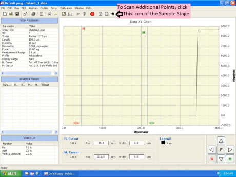
- Move R or M to selected points to read out of plane measurements (step heights).
- Drag R or M wider to read step heights that average over a wider area.
- Find the box “Watch List” to read results, or select different parameters to measure, such as ASH (average step height), Ra (roughness average), radius of curvature, etc. Right click in this box to change displayed parameters.
- In this example, 7A of Roughness was reported at the substrate. The step height displayed in the watch list is 0, because the sample has been leveled. Note the scale was 6.5um due to the sub 1um sample step height. If R was dragged to the right, the step height would be displayed in the watch list.
- If you wish to save data, choose the icon “Export Scan Data” which goes to a .csv file, which can be saved to a USB storage device.
- Move stage to next scan location, with knobs, but remember never touch the sample itself if at the Null tip height.
- Click “Sample Positioning” icon to view sample for further measurements.
- Choose icon “Raise Tip” when done, or whenever you want to touch your sample.
- When completed, remove sample, close door, close software “Dektak”, and disengage in CORAL.
|