- Authors: N. Desai, J. Yoo, A. P. Chandrakasan
- Sponsorship: Masdar Institute of Science and Technology (MIST)
Advancements in low-power electronics have opened up many opportunities to provide healthcare solutions through continuous, unobtrusive sensing of vital physiological signs. Power budgets and, by extension, size and cost of such sensors are now dominated by the communication costs, which have not scaled as rapidly [] . We are working on a topology and associated protocols customized for such networks that relax power requirements enough for the network itself to power sensors.
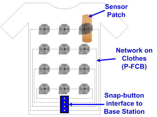
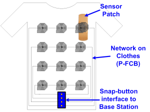
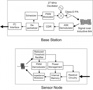
The network consists of clothing made from e-textiles containing a number of strategically-placed inductors screen-printed using a silver paste [] . Sensor Nodes (SNs) can be placed beneath any number of inductors. Power is transferred from the central Base Station (BS) to the SNs in the 27-MHz ISM band, which eliminates the need for bulky energy sources at each SN. Data from the SN is transferred at 1 Mbps through an impedance modulation link, similar to RFID, and is perceived as an ASK waveform by the BS. The high data rate allows each SN to have a very low transmit duty cycle (~1-2 %).
The medium-access protocol is designed to minimize the decision-making burden on the SN. Upon configuring the network, each SN is classified as a “Stream” mode (e.g., EKG, EEG) sensor or a “Contention Access (CA)” mode (e.g., blood pressure, glucose) sensor, which sends data infrequently. The BS assigns fixed timeslots to each stream-mode sensor. Once it has looped through all such sensors, it opens a CA period for the other sensors in the network. The protocol ensures that an SN always waits for a signal from the BS before transmitting and renders synchronization routines, such as the one presented in [] , unnecessary.
-
-
Figure 1: Architecture of e-textile network. Inductors on the fabric are arranged according to physical or functional proximity. A snap-button interface is used for connecting to the BS to avoid two inductive hops.
-
-
Figure 2: Block diagrams of Base Station and Sensor Node. Network access and configuration instructions are transmitted by the BS using an RZ PWM scheme to enable non-coherent detection at SN [4].Figure 2: Block diagrams of Base Station and Sensor Node. Network access and configuration instructions are transmitted by the BS using an RZ PWM scheme to enable non-coherent detection at SN [] .
- Authors: J. Yoo, L. Yan, D. El-Damak, M. Altaf, A. Shoeb, H-J. Yoo, A. P. Chandrakasan
- Sponsorship: Cooperative agreement between the Masdar Institute of Science and Technology and MIT, Reference No. 196F/002/707/102f/70/9374
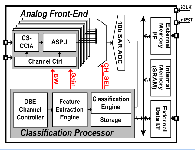
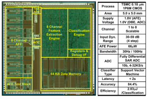
Continuous tracking of neurological disorders is crucial for the proper diagnosis and medication of epilepsy, and it mandates the design of ultra-low power sensor with a small form factor and continuous EEG classification. The main challenges arise from three factors: 1) variation in seizure pattern from person to person and age to age; 2) the need for wide dynamic range, low-noise AFE with high CMRR; and 3) the area overhead of integrating classification processor to enable seizure monitoring, detection, and storage in one chip. We present an ultra-low-power scalable EEG acquisition SoC for continuous seizure detection and recording with fully integrated patient-specific Support Vector Machine (SVM)-based classification processor. The proposed SoC is composed of 8 high-dynamic range Analog Front-End (AFE) channels, an SRAM and a patient-specific machine-learning seizure classification processor with a Feature Extraction (FE) Engine and a Classification Engine (CE). Each channel in the AFE integrates a Chopper-Stabilized Capacitive Coupled Instrumentation Amplifier (CS-CCIA) followed by an Analog Signal Processing Unit (ASPU). The SoC maintains high-accuracy seizure detection while minimizing the area overhead of the FE Engine by operating in two separate modes for seizure detection and recording. In seizure detection mode, the AFE uses a bandwidth of 30Hz with a 4-step adapted channel gain according to the signal strength. Once seizure is classified, the SoC automatically runs in seizure-recording mode at 100Hz bandwidth to store the EEG data in the internal SRAM. Digital filters are implemented using Distributed Quad-LUT (DQ-LUT) architecture, which enables area reduction for full integration of the classification processor. The SoC shows a detection accuracy of 84.4% in a rapid eye blink test while consuming 2.03μJ/classification.
-

-
Figure 1: EEG SoC architecture.
-
-
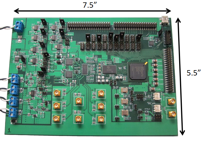
Figure 2: Chip micrograph and performance summary.
- Authors: B. Lam, K. Chen, S. Lee, C. G. Sodini, H.-S. Lee, A. P. Chandrakasan
- Sponsorship: Texas Instruments, SRC/FCRP C2S2
An ultrasound image is formed from a collection of ultrasonic beams transmitted and received by an array of transducer elements. As the resolution of an image and the range over which an image is to be formed increase, so do the number of these transducer elements and the corresponding digital processing units. The intensive signal processing power required for ultrasound imaging [] means that conventional ultrasound systems are often large and expensive, and this demand for processing power can only worsen as more transducers and signal channels are implemented. In applications such as point-of-care diagnostics in rural areas, the movement to a portable and low-power ultrasound imaging system is warranted.
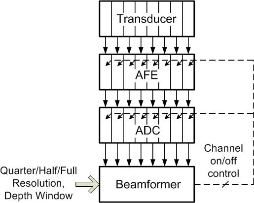
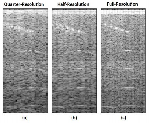
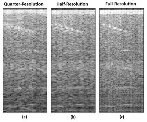
Beamforming, which in its simplest form involves delaying, scaling, and summing to produce a coherent signal from the collection of received beams, has been identified as an area for algorithmic research and development [] . In this work, an 8-channel wide, scalable digital beamformer is implemented with feedback for power reduction. Two modes of operation are available: coarse and fine beamforming. In the coarse beamforming mode, digitized data from an evenly spaced subset of transducer elements are processed, providing a low-quality image of the full region of interest, which yields power savings by turning off the analog front end electronics and analog-to-digital converters corresponding to the unused 50% or 75% of array channels (schematically shown in Figure 1). Figures 2a and b show the coarse images for quarter and half resolution coarse beamforming modes. Next, the user can specify a smaller region in which a higher quality image is desired, which is then beamformed by the same 8-channel wide processing unit using all available channels (an example of the full region full resolution image is shown in Figure 2c).
-

-
Figure 1: Ultrasound imaging system block diagram with feedback control for power reduction.
-
-
Figure 2: Comparison of beamformed images generated in the two coarse and one fine beamforming mode.
- Authors: M. Yip, A. P. Chandrakasan
- Sponsorship: Texas Instruments, NSERC
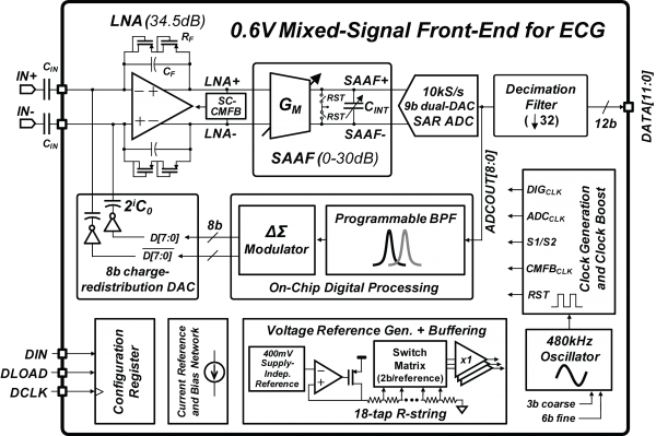
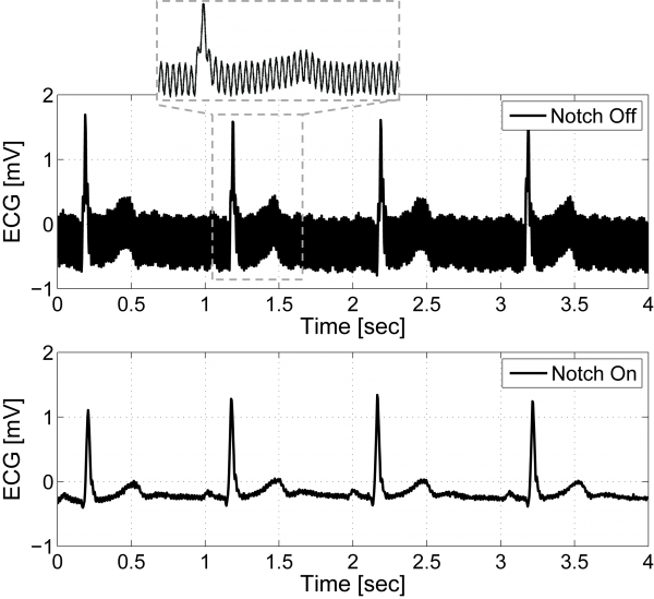
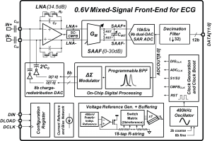
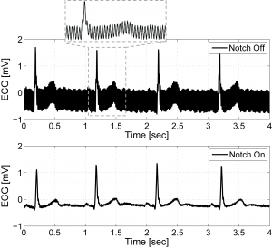
Circuits for wearable vital sign monitors have very stringent requirements on power dissipation due to limited energy storage capacity and the need for a long lifetime. Extending the time between battery recharge or replacement requires low-power electronics. We report a micro-watt mixed-signal front-end (MSFE) for ECG monitoring [] that uses aggressive voltage scaling to maximize power-efficiency and ensure compatibility with low-voltage DSPs [] . The MSFE shown in Figure 1 rejects 50/60Hz power-line interference (PLI) at the input of the system by using a mixed-signal feedback loop, enabling low-voltage operation by reducing dynamic range requirements. Analog circuits are optimized for ultra-low-voltage, and a SAR ADC with a dual-DAC architecture eliminates the need for a power-hungry ADC buffer. Oversampling and ΔΣ-modulation leveraging integrated digital processing are used to achieve ultra-low-power operation without sacrificing noise performance and dynamic range. Figure 2 shows ECG measurements on a male subject with the MSFE using gel electrodes and unshielded wiring. The PLI is clearly canceled when the PLI filter is enabled. The MSFE was prototyped in a 0.18µm CMOS process and consumes 2.9µW from 0.6V.
-
-
Figure 1: System block diagram of the mixed-signal front-end for ECG monitoring including all voltage and current references, and clock generation.
-
-
Figure 2: Measured ECG with the PLI notch filter disabled (top) and enabled (bottom).
- Authors: Y.-C. Hsiao, P. Triverio, T. Moselhy, J. White, L. Daniel
- Sponsorship: MIT-SkTech
Understanding certain medical conditions requires understanding specific aspects of the arterial blood flow. For instance, diagnosing atherosclerosis requires capturing detailed flow inside an arterial segment. Such study requires developing accurate solvers for the detailed equations describing both the blood flow and the elastic behavior of the arteries. At the other end of the spectrum, studying hypertension requires computing pressure and averaged flow over a larger arterial network. Such analysis requires developing compact computationally inexpensive models of complex segments of the arterial network. These models relate the pressure and average flow at the terminals of the arterial segments and must be easily interconnected to form complex and large arterial networks.
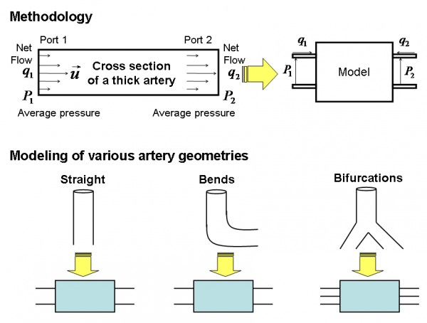
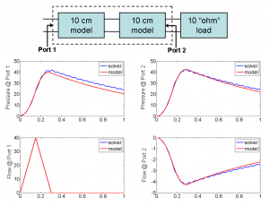
In this project we are developing a 2-D fluid-structure interaction solver to accurately simulate blood flow in arteries with bends and bifurcations. Such blood flow is mathematically modeled using the incompressible Navier-Stokes equations. The arterial wall is modeled using a linear elasticity model [] . Our solver is based on an enhanced immersed boundary method (IBM) [] . As a second step we are developing system identification techniques [] to generate passive models for complex arterial segments such as large arteries, arterial bends, and bifurcations. We have validated our solver results versus reference results obtained from MERCK Research Laboratories for a straight vessel of length 10 cm and diameter 2 cm. Our results for pressure, flow, and radius variations are within 3% of those obtained from MERCK. Furthermore, we are validating our model results by cascading different models and comparing the results of the resulting network to those predicted by our solver. Our preliminary results for pressure and flow at the terminals of the models are within 10% of those obtained from the full simulator. In addition, with our models we reduce the computational time by more than 100,000 times.
-

-
Figure 1: We use i) our immersed boundary method for incompressible Navier-Stokes to extract a complete model ii) our system identification technique to construct a reduced model [] . The lower part shows three major artery geometries we use for modeling a cardiovascular system.
-
-
Figure 2: A 20-cm artery is constructed by cascading two 10-cm artery models terminated with a matched load. The transient simulation results of the cascaded model are compared with those of a 20-cm artery solved by our immersed boundary method solver.
- Authors: A. Hochman, J. Villena, Z. Mahmood, L. Wald, E. Adalsteinsson, J. White, L. Daniel
- Sponsorship: NIH, MIT-SkTech
Two recent advances in Magnetic Resonance Imaging (MRI) technology have resulted in a need for sophisticated computational electromagnetics (CEM) tools. The first is the availability of higher fields scans that can improve signal-to-noise ratio. The second is the availability of transmit-coil arrays, which can be used to minimize human-body heating by electric fields. Higher fields imply higher-frequency RF pulses, with wavelengths comparable to the human body dimensions, which complicates electromagnetic analysis. They also imply increased tissue heating, which limits the RF power used for imaging purposes. In the computational prototyping group, we are developing CEM techniques to address these new needs of the MRI community, working in close collaboration with the RLE MRI group and the Harvard Massachusetts General Hospital MRI group, with some specific targets.
First, we are developing fast methods for tuning and matching the transmitters to the human-body loaded MRI coils. We combined scattering-matrix formalism, a frequency-domain finite-elements method, and commercial RF optimization software to reduce this process from days to hours. Also we plan to apply integral-equation methods to reduce it to minutes. Second, we are developing integral methods to allow for efficiently optimizing the geometrical configuration of the transmit coils. This hybrid approach will combine pre-computed Green’s functions for a realistic human body model with method of moments to be able to rapidly assess different coil configurations for a typical body. To aid this assessment, we plan to leverage our work on parameterized model-order reduction, automatically generating models depending on relevant parametric quantities. We are also working on fast methods for computing the approximate solutions to the electromagnetic fields inside the human body, assuming a simplified 3-tissue model that can be obtained for each patient by a quick MRI scan. Finally, we are developing an automated procedure for designing robust decoupling networks for arbitrary MRI transmission coil arrays, based on automatic nonlinear least squares techniques to compute the input impedance matrix, in opposition to currently applied manual methods, limited to small number of channels. These decoupling networks reduce the input power required for the same local increase of body heat vs. excitation fidelity.
-
-
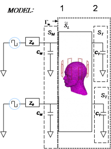
Figure 1: A scattering matrix formalism is used to generate a model for the transmit coils loaded by a human head. This model is then used in a commercial RF optimization package (RF Designer) to tune and match the coils to their drivers.
-

-
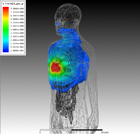
Figure 2: Electric fields generated by a 10A current source about 5 cm away from the chest, obtained by the commercial HFSS package. Similar calculations are performed for such sources at points around the body. These fields yield a numerically calculated Green’s function for the human body, which can then be used in an integral-equation method to rapidly assess different coil configurations.
- Authors: H. W. Hou, J. Y. Han
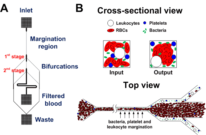
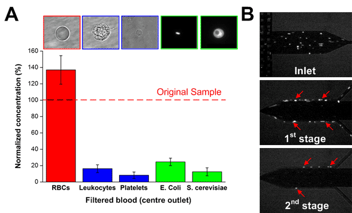
Sepsis is an adverse systemic inflammatory response caused by microbial infection in blood. In this work, we report a simple microfluidic approach for intrinsic, non-specific removal of both microbes and inflammatory cellular components (platelets and leukocytes) from whole blood, inspired by the in vivo phenomenon of leukocyte margination [] . As blood flows through a narrow microchannel (20 × 20 µm), deformable red blood cells (RBCs) migrate axially to the channel center, resulting in margination of other cell types (bacteria, platelets and leukocytes) towards the channel sides (see Figure 1) [] . With the use of a simple cascaded channel design, the blood samples undergo a 2-stage bacteria removal in a single pass through the device, thereby allowing higher bacterial removal efficiency. As an application for sepsis treatment, we demonstrated separation of Escherichia coli and Saccharomyces cerevisiae spiked into whole blood, achieving high removal efficiencies of ~80% and ~90%, respectively (Figure 2A). Inflammatory cellular components were also depleted by >80% in the filtered blood samples, which could help to modulate the host inflammatory response and potentially serve as a blood-cleansing method for sepsis treatment. The developed technique offers significant advantages including high throughput (~1mL/hr per channel) and label-free separation that allows non-specific removal of any blood-borne pathogens (bacteria and fungi). The continuous processing and collection mode potentially enables the return of filtered blood to the patient directly, similar to a simple and complete dialysis circuit setup. Due to design simplicity, further multiplexing is possible by increasing channel parallelization or device stacking to achieve higher throughput comparable to convectional blood dialysis systems used in clinical settings.
-
-
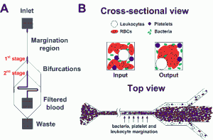
Figure 1: Schematic illustrations of the (A) microfluidic design and (B) separation principle. As blood flows through a narrow microchannel (20 × 20 µm, W×H), deformable RBCs migrate axially to the channel center, resulting in margination of other cell types (bacteria, platelets and leukocytes) towards the channel walls and subsequently removal from the side outlets while the center outlet collects the bacteria-depleted blood.
-
-
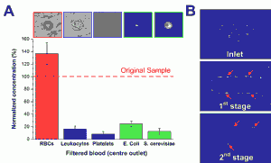
Figure 2: (A) Normalized concentration of different cellular components at the filtered center outlet using human whole blood spiked with Escherichia coli and Saccharomyces cerevisiae. (B) Optical images illustrating yeast filtration (red arrows) at different stages.
- Authors: M. K. Delano, E. S. Winokur, C. G. Sodini
- Sponsorship: Texas Instruments
With the escalating costs of hospital visits, clinicians are opting to use at-home monitoring devices to diagnose patients. Current ECG Holter monitoring devices typically have 24-48 hour memory and battery capacity [] . With many patients experiencing intermittent heart problems that can occur once every week or month, an event recorder or loop recorder is required [] . However, event recorders can save only up to a few minutes of ECG recordings. This constraint leads to the loss of most of the data, which could be very important in alerting the user to the onset of future episodes. Therefore, we have developed a Holter monitor prototype with the goal of battery and memory capacity of greater than one week. Figure 1 shows a block diagram of the system.
We based the long-term monitor prototype around a Texas Instruments MSP430 low-power microcontroller that enables high computing power with very low power consumption. The prototype monitor is mounted on standard 3M 2560 Red Dot electrodes. The central board is fabricated on a flexible PCB substrate. Mounting the PCB directly on the electrodes improves the SNR by an estimated 40 dB compared to using wired leads [] . The monitor is “L”-shaped with rounded corners and placed on the patient’s chest (Figure 2). The “L” shape enables several different ECG vectors to be recorded, depending on what the cardiologist wants to observe. The monitor has a micro SD card on board, which is enough to store weeks of ECG data sampled at 250 Hz continuously, without compression.
-
-
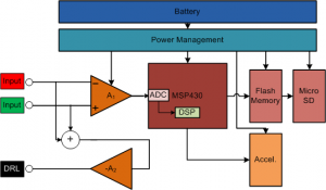
Figure 1: Block diagram of the ECG long-term Holter monitor system. The front end uses TI OPA333 and INA333 amplifiers and has a bandwidth from 0.5 Hz to 125 Hz. The 3-axis ADI accelerometer samples data at 12.5Hz to help correlate activity level with the ECG recordings. The battery is a 3.7V 600 mAh Li-Pol cell from Cameron-Sino.
-

-
Figure 2: A photo of the wearable, long-term cardiac monitor. The monitor is coated in Parylene C to protect it from water and sweat that may come in contact with the circuits.
- Authors: B. Do Valle, S. S. Cash, C. G. Sodini
- Sponsorship: CICS
Epilepsy is a common chronic neurological disorder that affects about 1% of the world population [] . It is characterized by repeated seizures, which are caused by an abnormal neuronal firing rate of the affected brain area. Although EEG has been the chief modality in the diagnosis and treatment of epilepsy for more than half a century, the vast majority of tests are performed in the hospital setting and are of brief duration. Long-term recordings (from days to weeks) can be obtained, but these must occur in the hospital setting. Many patients, however, have intermittent seizures occurring far less often (once a month or even less frequently). Capturing a seizure on EEG is a prerequisite for making a definitive diagnosis, tailoring therapy, or moving toward certain solutions such as surgery. For patients with infrequent seizures, capturing a seizure on EEG might require being in the hospital for over a month, which might not be possible. Thus, there is a need for a wearable long-term outpatient EEG monitor.
Our first prototype consists of 1 EEG channel sampled at 512 Hz with a 12-bit resolution. Figure 1 shows the simplified system block diagram. The data is stored in a micro SDHC flash card similar to the ones found in digital cameras.
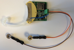
The system is housed in a hearing aid package as shown in Figure 2. One electrode is placed near the temporal lobe (close to T3), and the reference is placed on the mastoid.
-

-
Figure 1: Simplified system block diagram.
-
-
Figure 2: System prototype
- Authors: S. Pietrangelo, C. G. Sodini, H.-S. Lee
- Sponsorship: MIT Lincoln Laboratory Fellowship, Medical Electronic Device Realization Center
Traumatic brain injury (TBI) occurs in over 1.4 million persons annually in the United States [] . Monitoring of a patient’s cerebrovascular state following TBI is used in guiding therapy and mitigating secondary injury [] . Such monitoring, however, often relies on bulky capital equipment and a skilled operator, thus restricting its use to limited clinical environments (typically neurocritical care units). This project seeks to develop a low-power, miniaturized transcranial Doppler (TCD) ultrasound system for measuring cerebral blood flow velocity (CBFV) in support of continuous cerebrovascular monitoring.
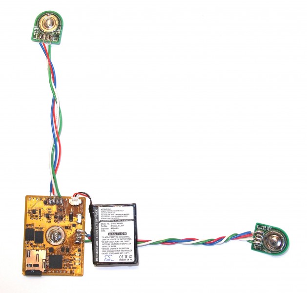
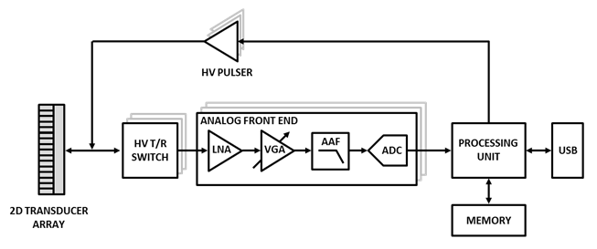
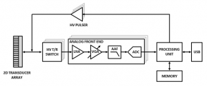
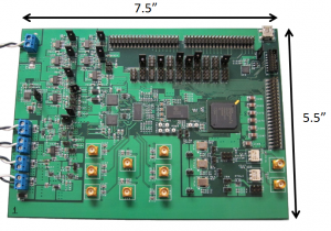
The system architecture, as illustrated in Figure 1, employs multi-channel transceiver electronics and a two-dimensional transducer array to permit electronic steering of the ultrasound beam. A first-generation discrete eight-channel TCD prototype is shown in Figure 2. Further revisions of the prototype system will increase channel count for improved beam steering functionality. Advanced beam steering algorithms will allow for autonomous vessel location, thereby obviating the need for manual transducer alignment and operator expertise. The wearable system will permit monitoring of cerebrovascular state in a wide variety of contexts that are currently unfeasible under standard measurement modalities.
-
-
Figure 1: Multi-channel TCD ultrasound system hardware block diagram.
-
-
Figure 2: Discrete eight-channel TCD ultrasound system prototype.