A 10-b, 1GS/s Time-interleaved SAR ADC with a Background Timing-skew Calibration
- Category: Circuits & Systems
- Tags: hae-seung lee, sunghyuk lee
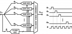
Figure 1 shows the block diagram of the proposed time-interleaved analog digital converter (ADC) with the associated timing diagram. The time-interleaved ADC is composed of a clock divider; a flash ADC; 8 time-interleaved SAR ADCs; and digital circuits for bit combining, output demultiplexing, and timing-skew calibration. The flash ADC resolves MSBs (4 bits) at the full speed (ɸ) of the time-interleaved ADC. The MSBs from the flash ADC are used as a coarse estimation of the SAR conversion. Each SAR ADC samples the input signal at a much lower speed (ɸX) and converts it into digital outputs. The MSBs of the SAR DAC are set by the flash ADC output and the remaining LSBs (7 bits including 1 bit redundancy) are resolved from the SAR conversion.
One advantage of the proposed ADC is that the flash ADC improves the conversion speed of each channel. In other words, the target conversion speed of the time-interleaved system can be met with fewer channels. Having fewer channels reduces the area and cost of the chip while it improves the yield of the chip.
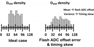
Another advantage of having a flash ADC that runs at full speed is that timing-skew can be estimated. Since the flash ADC does not suffer from timing-skew, the output of the flash ADC can be used as a golden standard for timing-skew calibration. A similar concept was presented in[1]. However, this work is different in that no extra channel is required to serve as a timing-skew standard. Figure 2 shows the idea of timing-skew calibration. When the sampling signal of the flash ADC and the sampling signal of the SAR ADC are not aligned due to a timing-skew, the coarse estimation from the flash ADC is inaccurate. To recover the error of the flash ADC, the SAR ADC output (DSAR) goes beyond the normal range. Thus, the variance of the DSAR can be used as a measure of the timing-skew. This calibration does not have any constraint on the input signal, and the calibration process does not interrupt the normal ADC operation. Thus, this calibration can be run in the background to track variations.
- Figure 1: Block diagram of the proposed time-interleaved SAR ADC.
- Figure 2: Timing-skew detection.
- M. El-Chammas and B. Murmann, “A 12-GS/s 81-mW 5-bit time-interleaved flash ADC with background timing skew calibration,” IEEE Journal of Solid-State Circuits, vol. 46, no. 4, pp. 838 –847, Apr. 2011. [↩]

