- Title: Assistant Professor
- Department: Department of Electrical Engineering and Computer Science
Collaborators
- Prof. Luca Daniel (MIT)
- Prof. Gary Fedder (CMU)
- Prof. Brian Otis (U. Washington)
- Prof. Muriel Medard (MIT)
Graduate Students
- Radhika Marathe (EECS)
- Wentao Wang (Mech. E)
- Laura Popa (Physics)
- Subramanian Sundaram (EECS)
- Steven Yee (EECS)
- Siping Wang (EECS)
- Bichoy Waguih (EECS)
Support Staff
- Valerie Dinardo, Administrative Assistant
Publications
Radhika Marathe, Wentao Wang, Dana Weinstein, “Si-based unreleased hybrid MEMS-CMOS resonators in 32nm technology” IEEE International Conference on Micro Electro Mechanical Systems (MEMS 2012), 729-732.
Wentao Wang and Dana Weinstein, “Acoustic Bragg reflectors for Q-enhancement of unreleased MEMS resonators,” IEEE Frequency Control Symposium (FCS 2011), San Francisco, CA, May 1-5, 2011.
Wentao Wang, Laura C. Popa, Radhika Marathe, Dana Weinstein, “An unreleased mm-wave resonant body transistor,” IEEE International Conference on Micro Electro Mechanical Systems (MEMS 2011), 1341-44.
- Authors: J. H. Lee, D. Weinstein, D. S. Boning
- Sponsorship: SRC/FCRP IFC
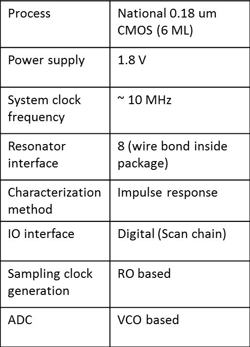
Electromechanical resonators such as quartz crystals, surface acoustic wave (SAW) resonators, and ceramic resonators have become essential components in electronic systems. However, due to their large footprint and difficulty in integrating with CMOS processes, there has been much development in realizing microelectromechanical system (MEMS) resonators that achieve comparable performance yet have smaller footprint and are compatible with CMOS. As with other semiconductor devices, with increasing frequency and with decreasing device size into the submicron scale, variability has started to become a critical issue in MEMS resonators. However, one of the critical challenges is the lack of a characterization method that is accurate but efficient enough to be used for testing the large number of devices necessary to acquire accurate statistical distribution of the parameters of interest. This project proposes an on-chip test circuit that can accurately characterize a large number of resonators for variation analysis and that is general enough that it can be used with a wide range of resonators, not limited to specific frequencies or other properties. The proposed test circuit is based on a transient step response method using a voltage step that can accurately measure the resonant frequencies and the quality factor of devices [] . The circuit employs a sub-sampling method to capture the high-frequency decay signal [] and a simple analog-to-digital converter (ADC) [] allowing complete digital interface, an important feature for test automation. SPICE level simulation combined with a behavioral simulation tool that was developed showed acceptable extraction errors of <1% for RS, <0.1% for Lx, <0.1% for Cx, <100 ppm for fs, and <1% for Qs. A test chip implementing the proposed test circuit has been designed and fabricated in NSC 0.18-um CMOS process.
-

-
Table 1: Detailed specification of the test chip.
-

-
Figure 1: Die photo of the fabricated test chip.
- Authors: Z. Mahmood, R. Marathe, D. Weinstein, L. Daniel
- Sponsorship: SRC/FCRP IFC, NSF, SRC/FCRP IFC, NSF
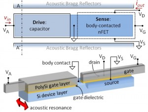
Design and optimization of novel RF Nano-Electro-Mechanical (NEM) resonators such as Resonant Body Transistors (RBT) require modeling across multiple domains, including mechanical (distributed stress and elastic wave models), electrical (semiconductor devices and RF small signal models), and thermal. These domains are all cross-coupled in nonlinear ways and require lengthy finite element multi-physics analyses to solve. Due to the complexity of these structures embedded in the CMOS stack and sensed using active FETs, the day-long time scale of each finite element simulation prevents quick, intuitive parameterization of device design. A reduced model parameterized across all three domains is therefore necessary both for rapid prototyping and for device optimization.
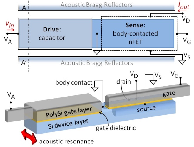
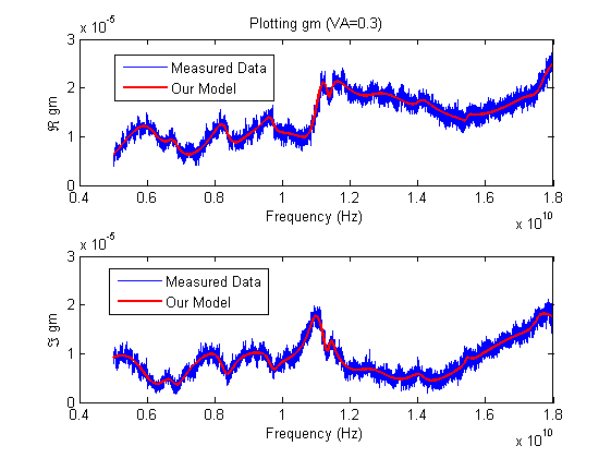
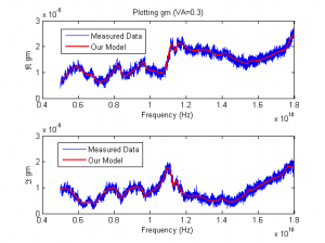
In this work, we are developing an algorithm to automatically generate compact models for NEM resonators. Our compact models are suitable for AC, DC and RF operation of the device and allow the circuit designers to run circuit-level time-domain simulations using any commercial circuit simulator [] [] . The compact models are “parameterized,” so that the circuit designer will be able to instantiate instantaneously models within the circuit simulator for different values of the key device parameters. Key resonator parameters included in the compact parameterized model are resonant frequency, quality factor, signal strength, isolation, presence of spurious modes, and operating temperature. Values for the model coefficients are calibrated using measurements from NEMS resonator devices. A critically important feature of our models is to guarantee that when circuit designers change arbitrarily values for the device parameters, the compact models will always preserve the physical properties of the original device and will never cause numerical instabilities and convergence issues when connected to other device models and circuits within the circuit simulator [] . Figure 1 shows the layout of a Si-based NEMS-CMOS resonator. Numerical results show a great promise for our technique. We have achieved high quality fit to the measured data, as Figure 2 shows, which offered modeling challenges including the presence of noise and spurious resonant peaks.
-
-
Figure 1: Top and 3D views of a Si-based NEMS-CMOS.
-
-
Figure 2: Plotting measured data (blue noisy line) and the output from out model (red smooth line) for controlling voltage VA=0.3V.
- Authors: R. Marathe, W. Wang, D. Weinstein
- Sponsorship: DARPA Young Faculty Award
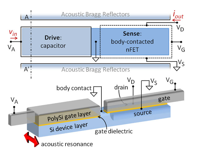
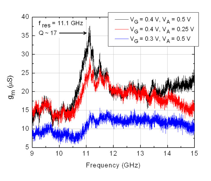
This work presents the first hybrid RF MEMS-CMOS resonators demonstrated in silicon at the transistor level of IBM’s 32-nm SOI CMOS process, without the need for any post-processing or packaging. The unreleased, Si bulk acoustic resonators are driven capacitively and sensed using a field effect transistor (FET). MEMS-CMOS Si resonators with acoustic Bragg reflectors (ABRs) are demonstrated at 11.1 GHz with Q~18 and a footprint of 5µm × 3µm.
The majority of electromechanical devices require a release step to freely suspend moving structures, which necessitate costly complex encapsulation methods and back-end-of-line (BEOL) processing of large-scale devices [] . Development of unreleased Si-based MEMS resonators in CMOS allows integration into front-end-of-line (FEOL) processing with no post-processing or packaging. We have previously demonstrated the Resonant Body Transistor (RBT), which employs active FET sensing of acoustic vibrations [] [] , which amplifies the mechanical signal before parasitics. Realization of the RBT in CMOS technology leverages high fT, high-performance transistors, enabling RF-MEMS resonators at frequencies orders of magnitude higher than possible with passive devices.
The hybrid MEMS-CMOS RBT presented in this work is a Si bulk-acoustic resonator with electrostatic drive formed using the gate dielectric and a body-contacted nFET sense transducer (see Figure 1). Acoustic vibrations in the unreleased resonator are confined using 7 pairs of 1D ABRs surrounding the device, which are patterned using shallow trench isolation (STI). The DC characteristics of the sense transistor are similar to standard body-contacted nFETs of the 32-nm SOI process and show no direct effect of the capacitor drive voltage on the FET behavior. The frequency response of an 11.1-GHz resonator is shown in Figure 2 for multiple bias conditions, verifying the mechanical nature of the resonance.
This first demonstration of an unreleased hybrid MEMS-CMOS resonator paves the way for monolithically integrated RF MEMS frequency sources and signal processors.
-

-
Figure 1: Top and 3D views of Si-based MEMS-CMOS resonator excluding ABR. The resonator is driven capacitively on the left and sensed as a piezoresistive modulation of the nFET drain current on the right. Source and body are independently grounded.
-

-
Figure 2: Frequency response of an 11.1-GHz nFET-ncap resonator under multiple biasing conditions of the drive voltage (VA) and gate voltage (VG).