A High-bandwidth, Digitally Assisted Phase Modulator
The purpose of this project is to design a building block for communications systems that produces a phase-modulated output based on a digital input. Although this particular work is intended in particular for the Asymmetric Multilevel Outphasing (AMO) architecture ( S. Chung, P. A. Godoy, T. W. Barton, Z. Li, T. W. Huang, D. J. Perreault, J. L. Dawson, “Asymmetric multilevel outphasing architecture for multi-standard transmitters,” in Proc. of IEEE Symposium on Radio Frequency Integrated Circuits, Boston, MA, June, 2009.)) , the basic function it performs is necessary in a variety of transmitter architectures. In most modulation schemes, information is encoded in the phase of the transmitted signal, so the transmitter must be capable of producing a precise phase-modulated signal. This capacity is certainly true of phase-shift keying (PSK), where the phase alone is modulated, as is quadrature amplitude modulation (QAM), in which information is encoded in both the amplitude and phase of the transmitted signal. Likewise, in architectures that rely on outphasing as in LINC [1] , amplitude modulation is performed through vector addition of precise, phase-modulated signals. The AMO architecture seeks to minimize the use of outphasing but ultimately relies on it for fine output control.
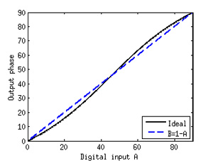
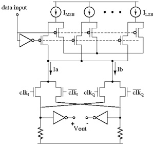
A high-bandwidth requirement makes a differential current-steering topology a logical choice. Weighted quadrature signals at the carrier frequency are combined to produce an output with an arbitrary phase shift as in [3]. Beyond this basic approach, this design takes advantage of its role in the larger system. In particular, digital predistortion is already in place due to other nonlinearities in the system that make it necessary. This allows for a phase modulator topology that constrains the possible inputs to the phase modulator so that the amplitudes of the two quadrature signals always sum to one. If the sine (A) and cosine (B) coefficients are thus constrained to be B=1-A, then the digital input simply corresponds to a particular magnitude for the coefficient A, and the resulting output phase has a nonlinearity as shown in Figure 1. In a digitally assisted system where this nonlinearity can be tolerated, this approximation has significant advantages for the phase modulator topology. A single set of binary weighted current sources can be used to produce coefficients A and B; each current source is steered either towards the in-phase (A) or quadrature (B) path. Using only one set of current sources eliminates the need to match across multiple sets of current sources as in [2] , and it nearly halves the required area. A simplified schematic is shown in Figure 2.
References
- D. Cox, “Linear amplification with nonlinear components,” IEEE Transactions on Communications, vol. 12, pp. 1942-1945, Dec. 1974. [↩]
- M. E. Heidari, M. Lee, and A. A. Abidi, “All digital outphasing modulator for a software-defined transmitter,” IEEE Journal of Solid State Circuits, vol. 44, pp. 1260-1271, Apr. 2009. [↩]

