Automated Wavelength Recovery for Microring Resonators
- Category: Optics & Photonics
- Tags: aleksandr biberman, michael watts, vladimir stojanovic
Silicon photonics is poised to meet the increasing demand for high-bandwidth, low-power, and densely integrated optical communications in CMOS-compatible environments. Microring resonators in particular have become ubiquitous photonic building blocks that have already been utilized to demonstrate modulators, filters, and switches. However, the large frequency dependence with geometry (~100GHz/nm) and thermo-optic coefficient (~10GHz/°C) innate to silicon microrings threatens to preclude their use in dense wavelength division multiplexed (DWDM) applications, where the channel spacings are tight and temperatures may vary by as much as 15°C. Several promising solutions to address this challenge have come in the form of low-power (4.4µW/GHz) and high-speed thermal tuning, sensor-based thermal compensation, and athermal devices. However, while temperature sensor and athermal solutions address the thermal stability issue, they do not address fabrication based frequency variations. A recent study has leveraged scattering of the microring filters for wavelength locking; however, scattered light based techniques are insufficiently reliable to enable large-scale implementations.
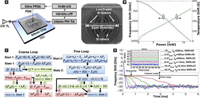
In our work [1] , we experimentally demonstrated the first high-speed and scalable on-chip optical wavelength recovery capable of compensating both fabrication and thermal induced frequency variations on a silicon photonic chip. Using a thermally tunable adiabatic resonant microring (ARM) resonator, shown in Figure 1a, combined with a unique wavelength recovery algorithm implemented using a field-programmable gate array (FPGA), we demonstrate low-power (less than 1mW for ±10°C) and high-speed (as low as 200 µs) wavelength recovery. Furthermore, this approach is capable of being implemented using advanced CMOS electronics, hybrid or monolithically integrated with silicon photonics. The implemented algorithm and the experimental results are depicted in Figure 1. Using the algorithm, the recovery time is experimentally reduced from 4.3ms to 200µs.

Figure 1: A) Diagram of the experimental setup for wavelength recovery using the ARM resonator and top-view scanning electron microscope (SEM) image of the device. B) Measured frequency shift and calibrated temperature shift as a function of heater power. C) Coarse and fine loop flow charts for wavelength recovery decision-making for thru port where PH(t) is real-time power dissipated in the heater; ΔPH(t) is real-time power variation in the heater; PMAX/MIN is maximum/minimum heater power; ΔPC/F is coarse/fine minimum power variation in the heater; I(t) is real time output intensity; I0 is the threshold intensity; e(t) is the error signal; and IT(t) is the target intensity, which is constantly updating for global minima locking. Drop port decision-making algorithm can be implemented by changing comparison statements and using the rest of the algorithm. D) Microring wavelength recovery results as a function of increasing minimum power variation in the heater and stability of the recovered signal is investigated as a function of loop speed (inset).
- E. Timurdogan, A. Biberman, D. C. Trotter, C. Sun, M. Moresco, V. Stojanović, and M. R. Watts, “Automated wavelength recovery for microring resonators,” in Proc. Conference on Lasers and Electro-Optics, CM2M.1 2012. [↩]